PID Tuning for Mobile Robots: A Field Guide
Most PID tuning guides start with transfer functions and Ziegler-Nichols tables. Useful in theory, but on an actual robot with backlash, wheel slip, and a battery voltage that sags under load, the textbook method gets you in the neighborhood at best. What actually gets a loop tuned is a repeatable procedure and a way to look at the response.
The controller itself is just three terms acting on the error between setpoint and measurement:
Ziegler-Nichols gives a starting point from a single experiment: push proportional gain alone until the loop sustains a constant-amplitude oscillation, record that ultimate gain and oscillation period , then compute:
It's a reasonable first guess, not a finish line — real hardware nonlinearity is exactly why the empirical pass below still matters.
Start with P alone, and go further than feels comfortable
Zero the integral and derivative gains and raise proportional gain until the system oscillates around the setpoint. That oscillation point isn't a mistake — it's calibration data. Most guides tell you to back off at the first sign of overshoot; in practice, pushing slightly past first-oscillation and then adding damping through derivative gain gives a stiffer, more disturbance-rejecting loop than staying conservative on P the whole time.
Add D before I
Derivative gain fights the oscillation you just created and lets you keep more proportional gain than you could otherwise. Only once the response is reasonably damped should integral gain go in — and only enough to kill steady-state error, since I gain is the term most likely to introduce slow, low-frequency oscillation that's hard to diagnose later because it shows up seconds after the disturbance, not immediately.
Tune on the actual robot, not the bench
A wheel spinning freely in the air has none of the load inertia, friction, or wheel slip of the same wheel on the floor. Gains tuned on a bench routinely need re-tuning once the robot is loaded and moving on its real surface — budget time for it instead of being surprised by it.
Case study — warehouse robot drive loop
An autonomous warehouse robot's wheel velocity loop was originally tuned on blocks, with the wheels spinning free. On the floor with a full payload, the same gains produced a visible low-frequency wobble during acceleration — barely noticeable empty, uncomfortable at full load, and enough to trip the robot's own slip-detection safety stop.
Retuning on the actual floor surface with a loaded payload — following the P-then-D-then-I sequence above — removed the wobble entirely and cut the time to reach commanded velocity from roughly 900 ms to under 300 ms, without tripping the slip detector. The bench-tuned gains weren't wrong, they were tuned for a different physical system than the one the robot actually operates in.
None of this replaces a proper stability analysis when the application calls for one — but for most small mobile robots, a disciplined empirical tuning pass gets you a controller that's both stiffer and more forgiving than a "safe" set of gains that's never been pushed to its limit.
Related Project
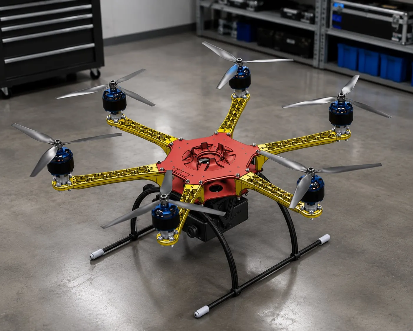
Autonomous Rescue Drone — Smart Summer Summit v2
More