Topology Optimization: Cutting Weight Without Cutting Corners
Topology optimization software is very good at answering one question: "given this design space, these loads, and this amount of material to remove, what shape carries the load most efficiently?" It is much worse at answering the question engineers actually care about, which is "can this part be made, assembled, and inspected?"
What the solver actually optimizes
Give a topology optimization run a design space, boundary conditions, and a target mass fraction, and it will return an organic-looking shape that minimizes compliance (maximizes stiffness) for that mass. It's genuinely good at finding load paths a human wouldn't intuitively draw — material collects along the lines of principal stress and disappears everywhere else.
The catch is that the raw output is a mesh, not a manufacturable part. Every result needs a reinterpretation pass: smoothing the geometry, adding fillets a tool can actually cut, and — critically — re-running a full FEA validation on the reinterpreted CAD, not the raw optimizer output.
The math underneath: SIMP
Most commercial solvers use some variant of SIMP (Solid Isotropic Material with Penalization). Every element gets a fictitious density , and its stiffness is interpolated as a penalized power of that density:
With a penalty exponent (typically 3), intermediate densities become structurally inefficient compared to fully solid or fully void material, which pushes the optimizer toward a crisp 0/1 layout instead of a mushy gray part. The optimization problem itself is compliance minimization under a volume constraint:
where is the displacement field and the global stiffness matrix assembled from the element densities. This is exactly the formulation behind the well-known "88-line" MATLAB topology optimization code that's taught in most graduate structural optimization courses — the core loop looks like this:
function SIMP_OPTIMIZE(mesh, volfrac, p, rmin):
    rho ← volfrac * ones(n_elements)
    loop:
        U ← solve_FE(K(rho))                # K assembled with E(rho_e) = rho_e^p * E0
        c ← U' * K(rho) * U
        dc ← -p * rho.^(p-1) .* element_compliance(U)
        dc ← mesh_filter(dc, rho, rmin)     # prevents checkerboarding and mesh dependency
        rho_new ← optimality_criteria_update(rho, dc, volfrac)
        if max(abs(rho_new - rho)) < tol:
            return rho_new                  # converged density field
        rho ← rho_new
Where teams get burned
- Ignoring manufacturing constraints at setup time. If the part will be machined from billet, you need draft-free, tool-accessible geometry from the start — adding manufacturing constraints to the optimization run itself (extrusion, symmetry, minimum member size) saves a full redesign cycle later.
- Trusting the raw mesh stress plot. The optimizer's own stress results are on an unrefined, non-manufacturable mesh. They tell you almost nothing about the stress in the part you'll actually build.
- Optimizing for a single load case. A bracket that only ever sees one static load in the model but three different loads in service will optimize itself into something that fails the load case nobody modeled.
Case study — robot arm end-effector mounting bracket
A mounting bracket connecting a gripper to a 6-axis arm was originally a machined aluminum block sized by intuition and a large safety margin. Running a topology optimization with the actual duty cycle (pick load, worst-case acceleration, and a secondary torsion case from an off-axis grab) as three combined load cases returned a distinctly non-obvious rib pattern.
After reinterpreting the geometry with machinable fillets and re-validating with a full FEA pass across all three load cases, the bracket dropped from 2.40 kg to 1.35 kg — a 44% mass reduction — while keeping the same 2.5x safety factor on yield. On a fast-moving arm, that mass reduction directly reduced motor torque requirements and settling time at each pick point.
Topology optimization isn't a shortcut around engineering judgment — it's a very effective way to generate a starting point that a human still has to turn into a real part.
Related Project
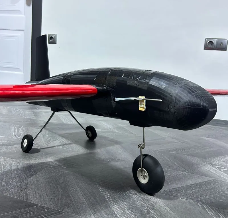
UAV Aerodynamic & Structural Optimization
More