Project
Single-Plate Clutch Assembly Design — Siemens NX
Technology
Year
2024
Context
Personal project to design a complete single-plate clutch assembly in Siemens NX using a bottom-up assembly approach, aimed at understanding the mechanical architecture, component interactions, and power transmission principle of a single-disc clutch.
Constraints
All 19 components — bearings, shafts, gears, friction disc, springs, toggle levers, pins, and rivets — had to be individually modeled to standard fasteners and geometry (including an ISO 4014 M10 bolt) and then assembled bottom-up into one coherent, correctly constrained mechanism.
My Role
Sole designer: modeled all 19 individual components, defined every assembly constraint and mating relationship using a bottom-up methodology, and built the complete single-plate clutch assembly in Siemens NX.
Approach
Component modeling. Each of the 19 components — ball bearing, bracket, brass bush, clutch plate, driven flange, driven shaft, friction disc, spring, spur gear, toggle lever, pins and rivets among them — was modeled individually, including a standard ISO 4014 M10 bolt.
Bottom-up assembly. Components were brought together following a bottom-up methodology: each part is designed independently first, then assembled and constrained, rather than driving geometry top-down from a master assembly sketch.
Power transmission architecture. The clutch plate is positioned between the flywheel and pressure plate; the assembly was built around the engagement path so that, when engaged, friction between the clutch plate and surrounding surfaces transmits torque through to the driven shaft.
Mechanical detail. Friction linings and torsional springs were incorporated into the clutch plate to contribute to torque transmission and absorb torsional vibration, alongside the toggle levers, pressure springs, and rivets that hold the pressure-plate assembly together.
Results
Complete, correctly constrained 19-component single-plate clutch assembly modeled bottom-up in Siemens NX, demonstrating the full friction-based power transmission path from flywheel to driven shaft.
Limitations
No stress, wear, or thermal analysis was performed on the friction and spring components — the goal was assembly methodology and mechanical architecture, not performance validation.
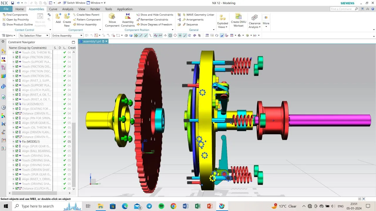
Full assembly, exploded — driven flange, friction disc pack, and driving shaft
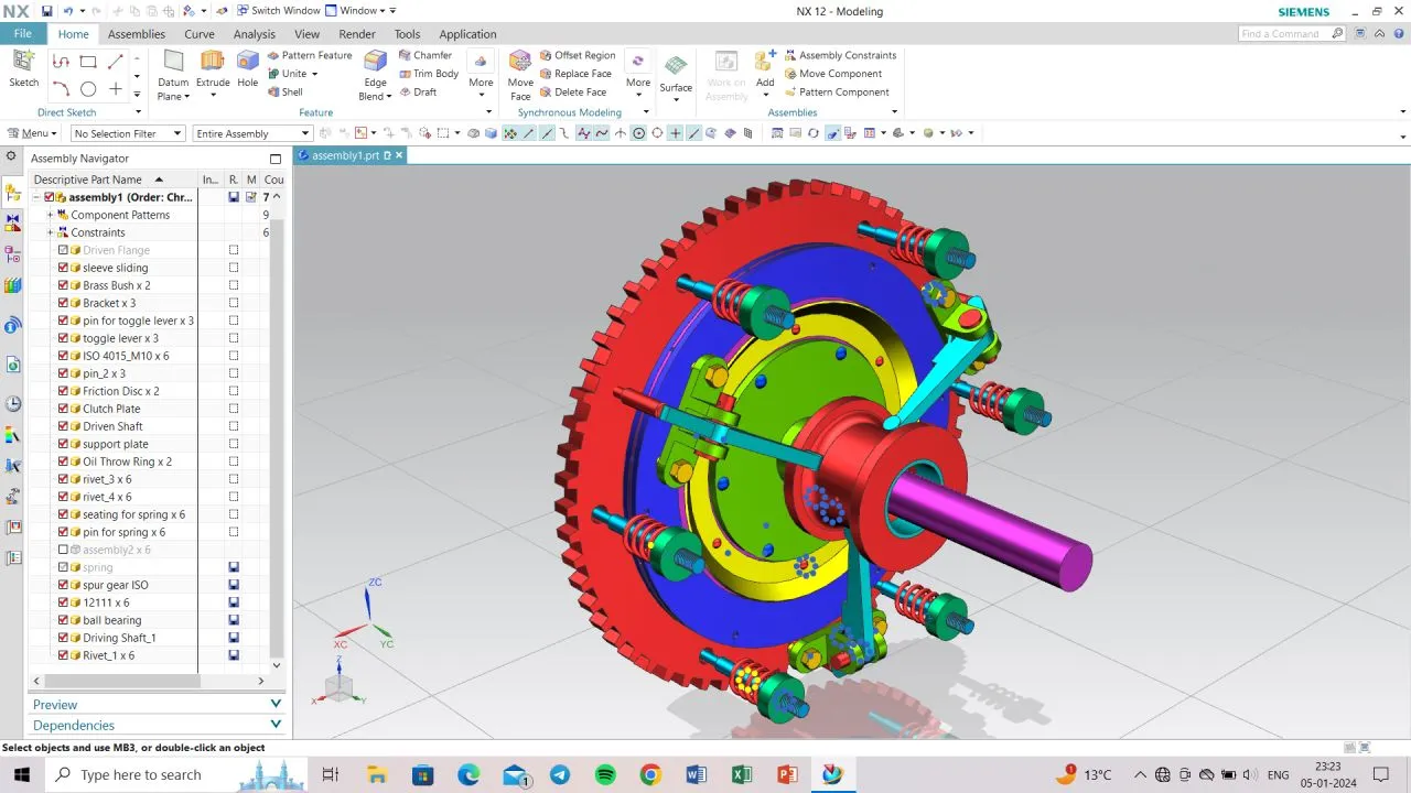
Assembly structure — all 19 components in the Assembly Navigator
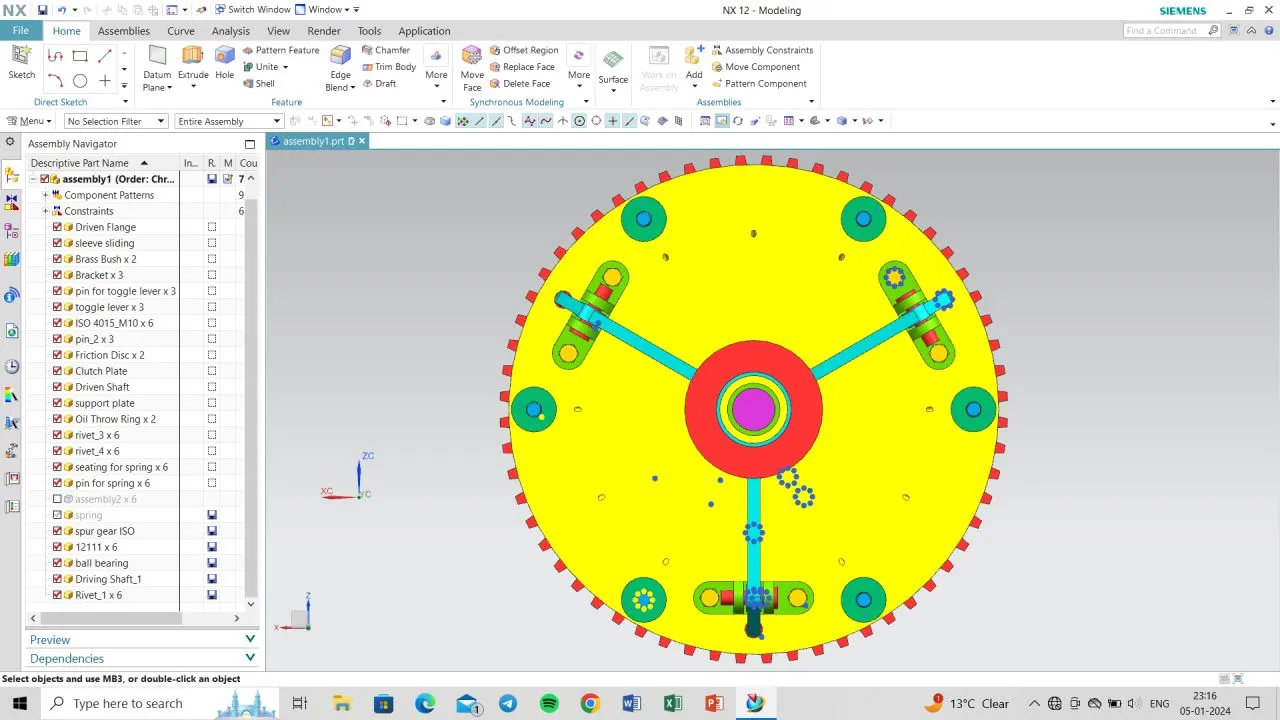
Front view — toggle levers and springs arranged around the clutch plate
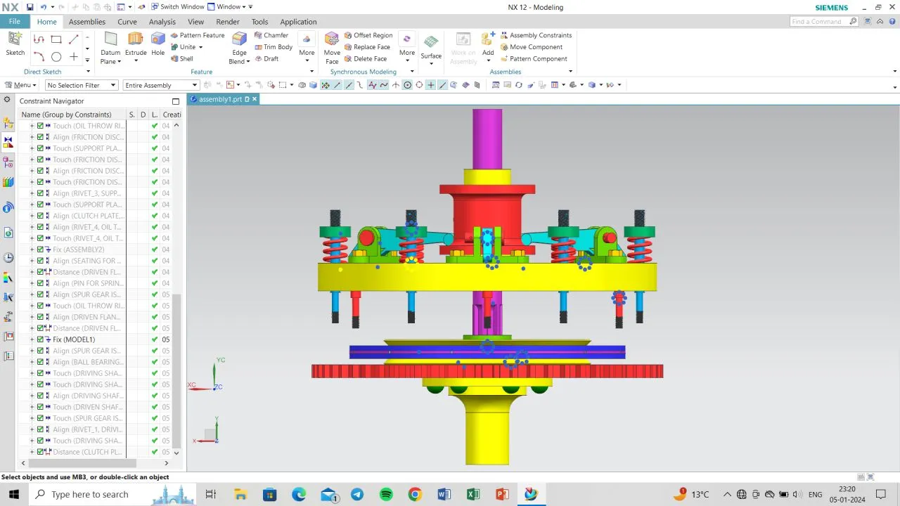
Side elevation — spring, toggle lever, and pressure plate stack
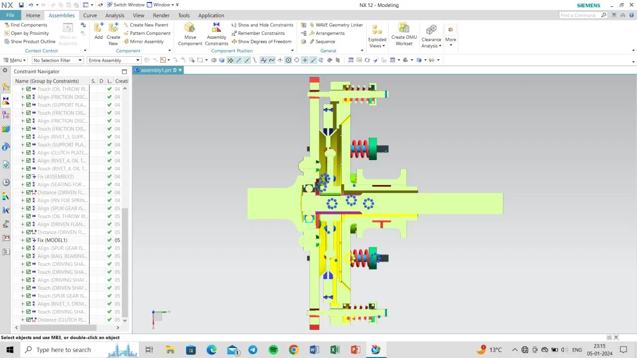
Sectioned assembly — internal bore, bearings, and spring arrangement
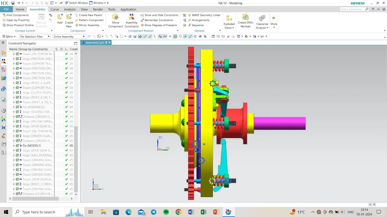
Assembly constraints — mating the friction disc pack and support plate
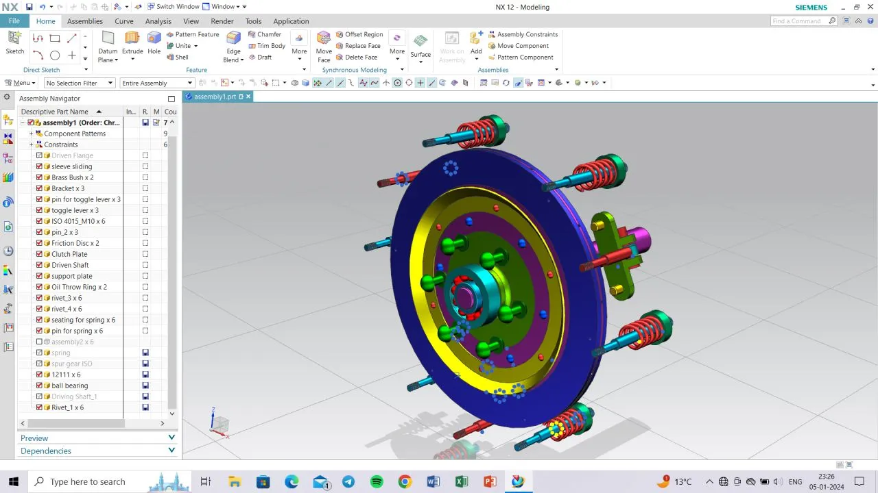
Isometric view — driven flange, spur gear, and shaft assembly
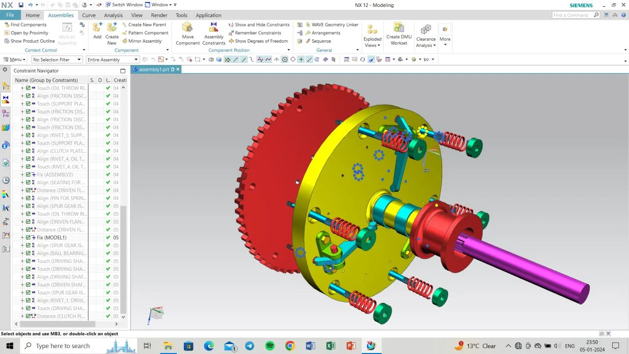
Isometric view — driving shaft and clutch plate assembly