Project
Custom CNC Metal Lathe — Mechanical Design of a Precision Machine Tool
Technology
Year
2024
Context
Small commercial lathes force a compromise: hobby-grade machines are built from thin welded steel or light cast iron, and the resulting lack of rigidity and damping shows up directly as chatter, poor surface finish, and limited depth of cut. Industrial machines solve this with heavy cast iron beds — but casting and stress-relieving iron is not something you can do in a workshop. This project set out to design a compact CNC lathe that reaches industrial-class rigidity and vibration damping using materials and processes available outside a foundry, by designing the structure around epoxy granite and buying in only the components that genuinely require ground precision.
Constraints
The frame had to damp vibration without access to cast iron founding or stress-relief annealing.
Every machined part had to be producible from standard steel and aluminum stock using conventional machining.
Epoxy granite has high compressive strength but poor tensile strength: no load could be taken directly by the casting, and no threaded feature could be cut into it.
The casting cannot be re-machined afterwards, so every mounting interface had to be positioned to final tolerance before the resin cured.
Spindle and tailstock accuracy depends on bearing preload and ground running surfaces — out of reach of in-house manufacturing.
The drivetrain had to be sized around a 1500 W AC servo.
My Role
Sole designer of everything structural: the epoxy-granite frame and its embedded steel inserts, the carriage, axis guidance, and drivetrain integration, plus sizing and integrating the servo drive, CNC control, and limit switches. The spindle and tailstock were bought off-the-shelf, not designed.
Approach
Frame material selection. Epoxy granite was chosen over welded steel and cast iron on damping. A mineral casting typically damps vibration several times better than cast iron and roughly an order of magnitude better than a welded steel structure, which is decisive on a lathe where chatter sets the practical limit on depth of cut and surface finish. It also cures with essentially no residual internal stress, so the frame stays dimensionally stable over time without the annealing cycle a welded or cast structure needs. The trade-offs are real and I designed around them: low tensile strength, a cure time measured in days, and a one-shot geometry that cannot be corrected by machining.
Load paths. Because nothing can be bolted into the casting itself, all mechanical interfaces run through steel inserts embedded in the mold. Each insert was positioned and aligned in the mold to its final tolerance before pouring, and sized so that machining loads are transferred into the mineral mass in compression rather than as tension or shear at the resin interface.
Make versus buy. The spindle and tailstock were bought off the shelf from a Grizzly lathe. Spindle accuracy is a function of bearing preload and ground running surfaces, and reproducing that without grinding capability would have cost far more precision than it gained. Everything structural — the frame, the carriage, the axis mounts and the drivetrain integration — was designed in-house, which is where the design work actually adds value.
Motion and precision chain. The carriage, axis guidance and transmission were designed around the tolerance chain running from the spindle axis to the tool tip: guideway alignment, backlash management in the drive, and the stack-up of every interface between the two. Controlling that chain, rather than any single component tolerance, is what determines the accuracy the machine can actually hold.
Drive sizing and mechatronic integration. The 1500 W AC servo was sized from target cutting forces across the intended workpiece diameter range and material set, together with the required spindle speed range. Servo drive, CNC control and limit switches were integrated into the mechanical design from the start rather than fitted afterwards — the kind of combined mechanical and electronic design work that sits at the center of my mechatronics background.
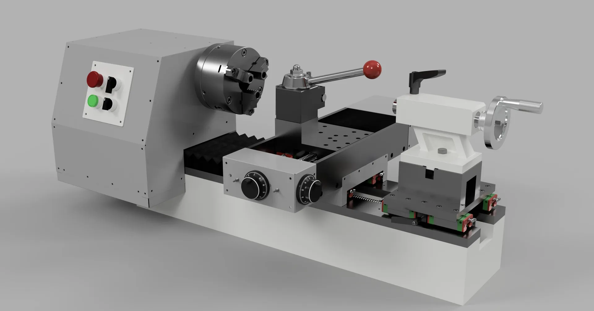
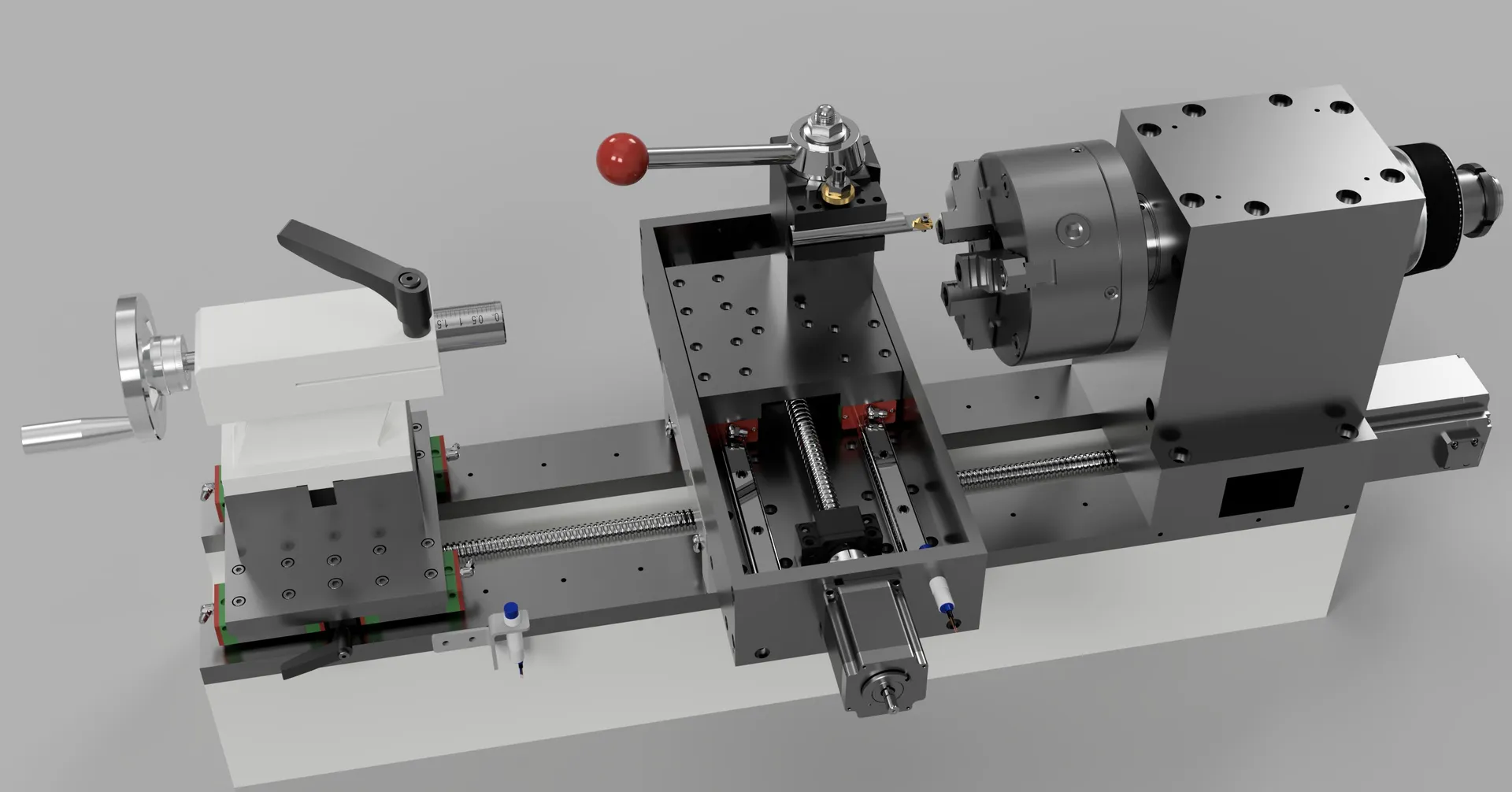
CAD assembly — headstock, chuck, and cross-slide
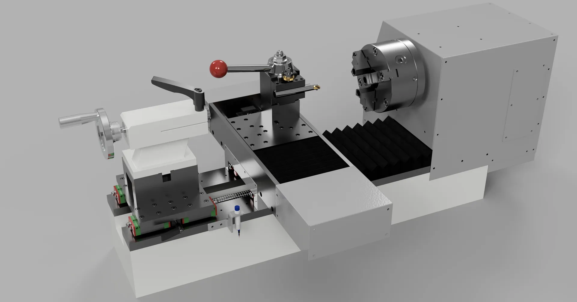
CAD assembly — tailstock and bed, viewed from the opposite side
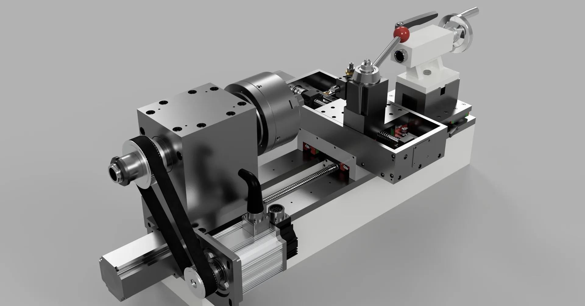
Drivetrain detail — spindle motor and belt drive
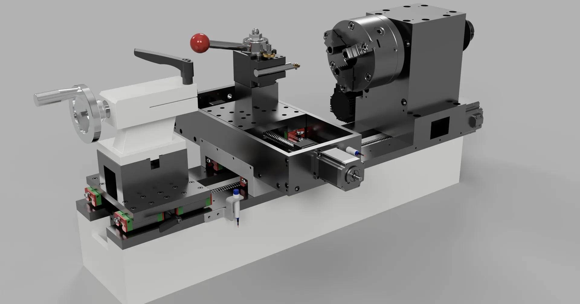
Carriage and tool post, with the spindle drivetrain in the background
Tool post and graduated cross-slide dial, close-up