Project
Jet Engine Assembly Design — Creo Parametric
Technology
Year
2026
Context
Personal challenge to design and assemble a complete jet engine in Creo Parametric within two weeks, focused on understanding the architecture, component relationships, and mechanical integration of a complex engineering system rather than modeling geometry in isolation.
Constraints
The full engine — turbine stages, bearing cases, shafts, casings, and exhaust — had to be modeled and integrated into one coherent, correctly constrained assembly within a two-week timeframe, entirely self-directed with no existing reference assembly to build from.
My Role
Sole designer: modeled every individual component, defined all assembly constraints and mating relationships, and built the complete jet engine assembly from scratch in Creo Parametric, including section and exploded views for internal visualization.
Approach
Component modeling. Each part — turbine blade rings, bearing cases, shafts, casings, exhaust cone — was modeled individually using advanced 3D part modeling techniques, focusing on the geometry each component actually needs to fulfill its role in the assembly.
Assembly and constraints. Components were brought together into a single large assembly, with constraints and mating relationships defined to accurately reflect how the parts locate and move relative to each other — the core challenge of large mechanical assembly design.
System architecture. Rather than treating the engine as a collection of unrelated parts, the modeling process was driven by understanding how the different engine components interact within the overall system.
Visualization. Section and exploded views were used throughout to study and communicate the internal structure of the assembly — a standard engineering visualization technique for validating that a design is both correctly built and understandable to others.
Results
Complete, correctly constrained jet engine assembly modeled from scratch in two weeks, integrating dozens of components across the turbine, bearing, shaft, and casing systems.
Limitations
No stress, thermal, or CFD analysis was performed — the goal was CAD architecture and assembly mastery, not performance validation.
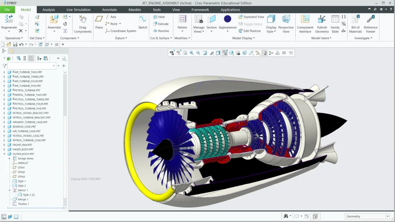
Cutaway view of the assembled engine — turbine stages, shaft, and casing architecture
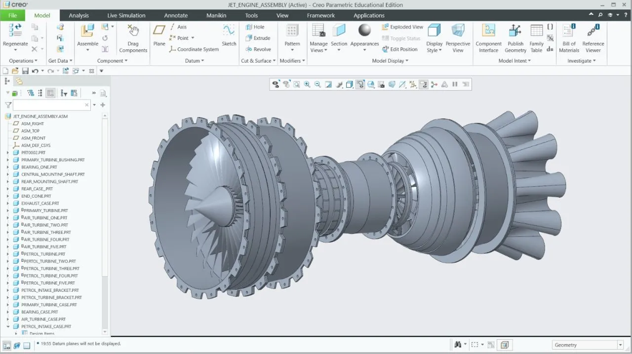
Fully assembled engine, front rotor stage in section
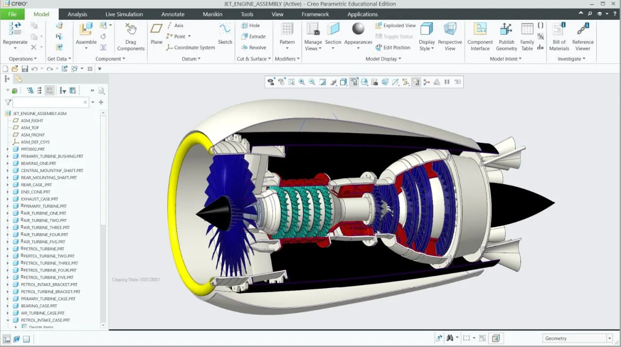
Sectioned assembly — internal turbine stage layout
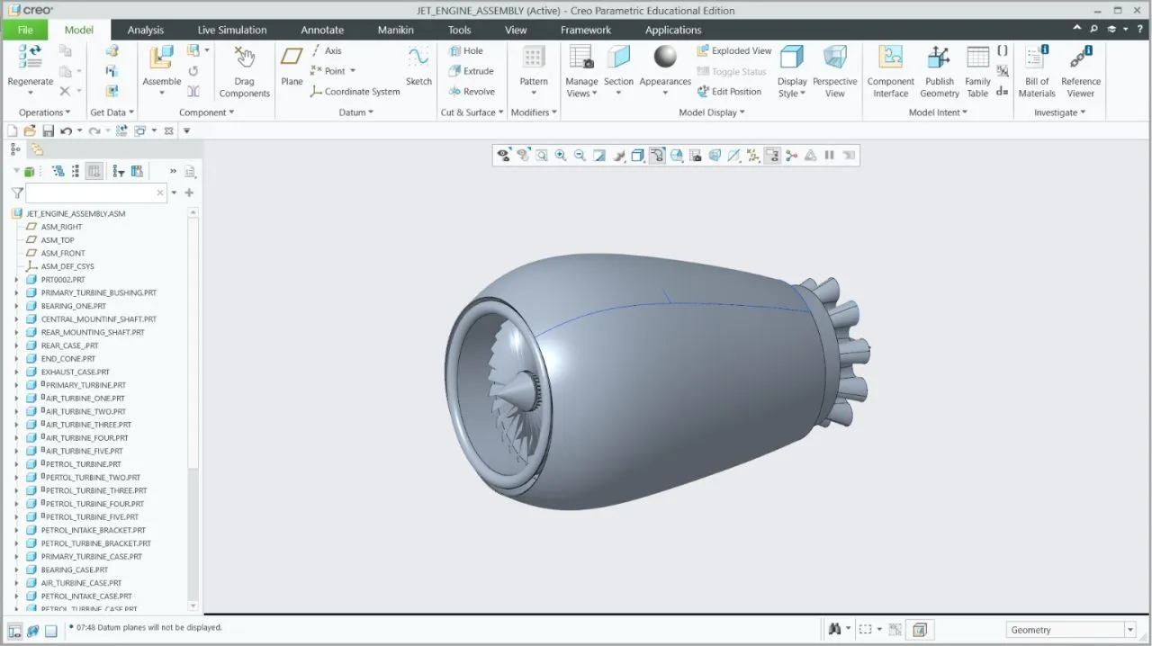
External view — intake cone and outer casing
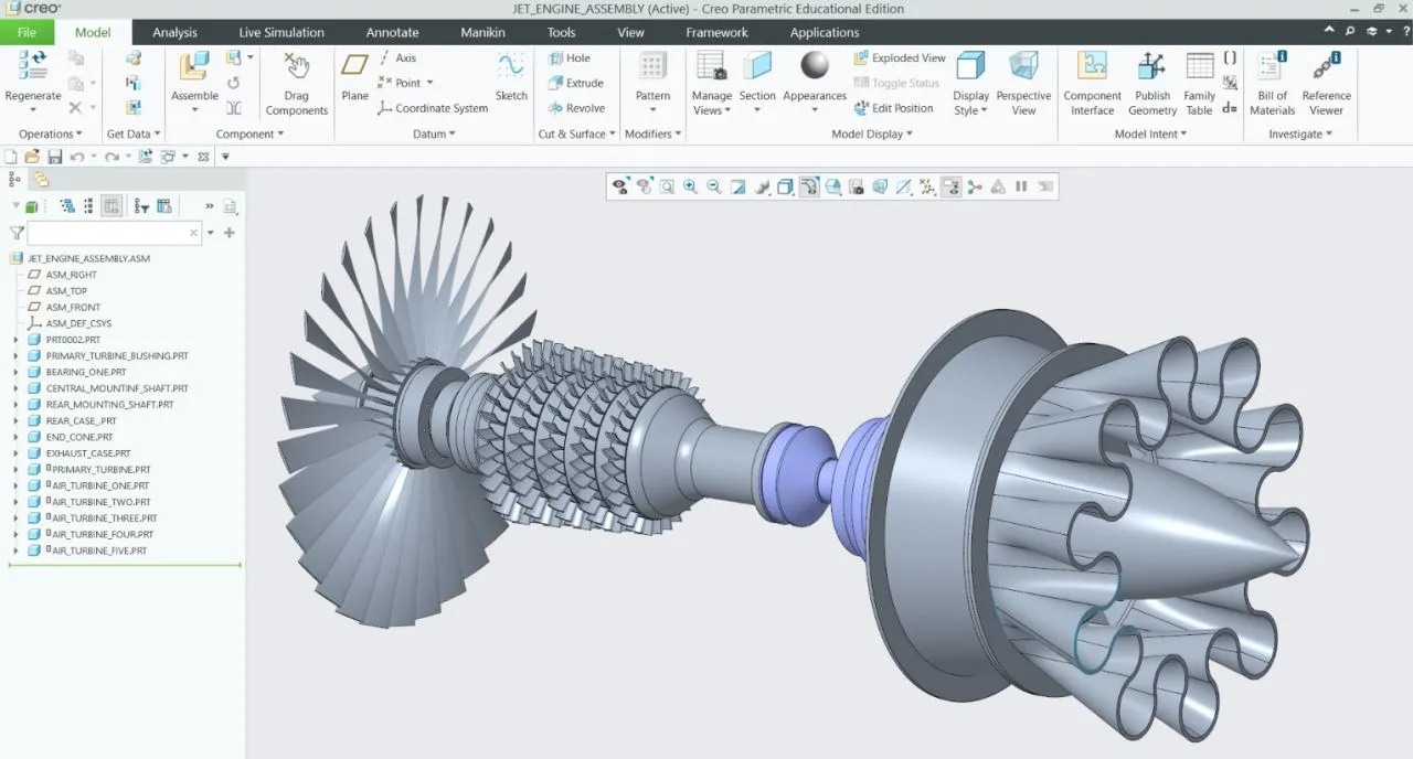
Exploded view — turbine rotor, shaft, and exhaust nozzle cluster
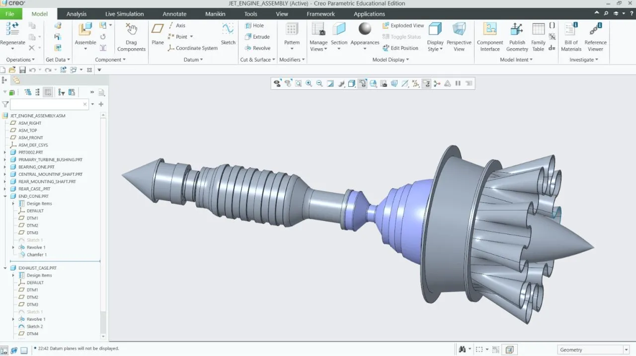
Shaft assembly — rotor-to-nozzle component chain
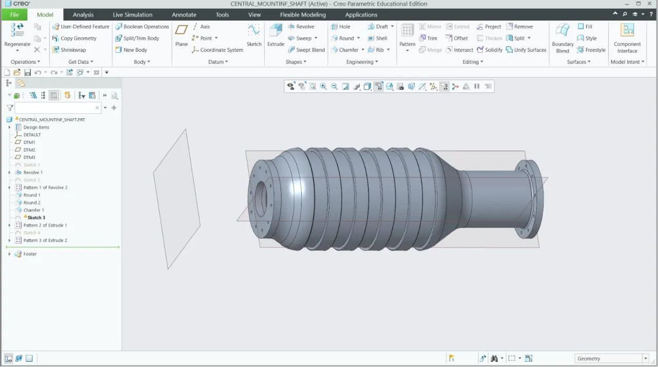
Central mounting shaft — individual part model
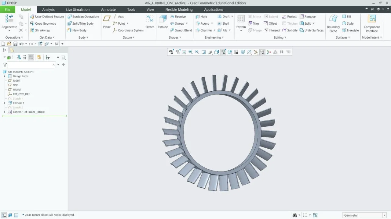
Turbine blade ring — individual part model
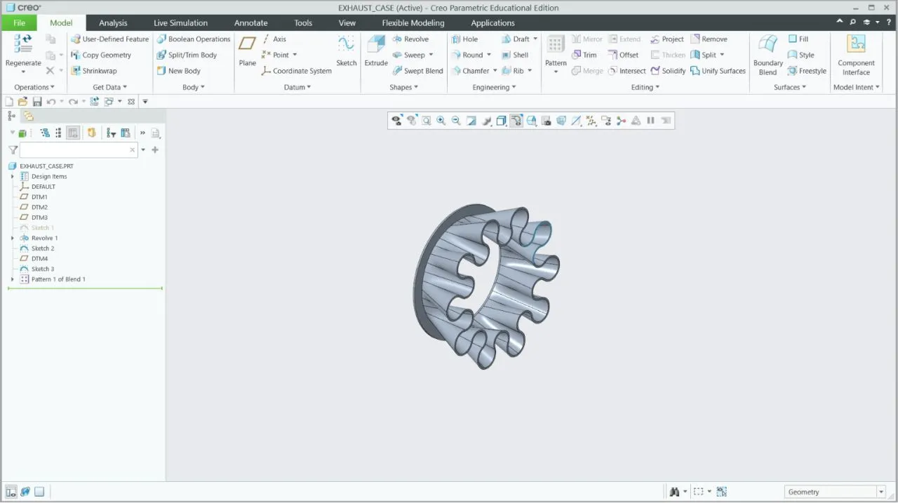
Exhaust case — individual part model
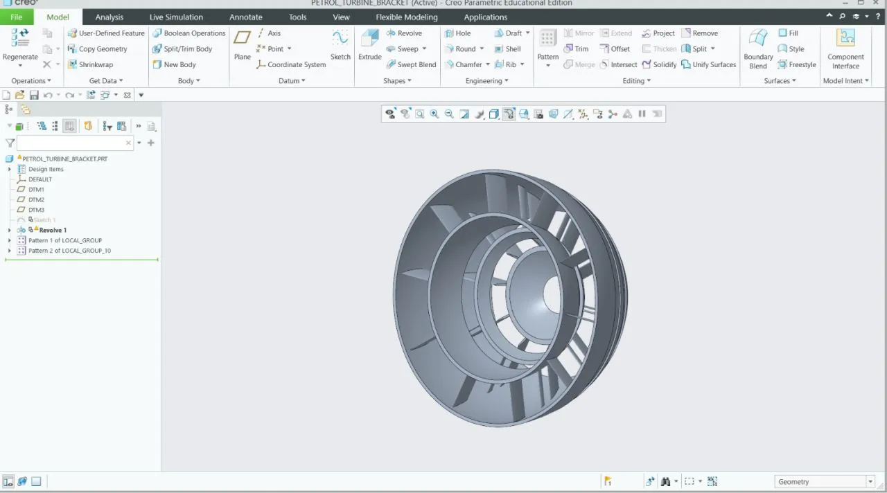
Turbine bracket — individual part model
Full assembly walkthrough — Creo Parametric