Project
Robotic Arm Assembly & Motion Simulation — Siemens NX
Technology
Year
2026
Context
Personal project to design a complete robotic arm in Siemens NX, moving beyond static part modeling to build a functional, animated mechanical assembly with configured joints and simulated motion.
Constraints
Every component had to be modeled individually and then assembled with constraints and joints accurate enough to reproduce the arm's intended range of motion, culminating in a coherent animated motion sequence rather than a static assembly.
My Role
Sole designer: modeled every individual component, built and constrained the full assembly, configured the joints and degrees of freedom, ran the motion simulation, and produced the final animation in Siemens NX.
Approach
Part modeling. Each robotic arm component — base, links, joints, gripper — was individually designed and detailed in Siemens NX before being brought into the assembly.
Assembly and constraints. Components were integrated into a complete assembly, with mechanical relationships and positioning defined through assembly constraints so every part locates correctly relative to the others.
Mechanism development. Joints and degrees of freedom were configured to reproduce the arm's intended movements, turning a rigid assembly into a working mechanism.
Motion simulation and animation. The mechanism's movement was validated through motion simulation, then captured as a complete animated sequence to visualize and communicate the final design.
Results
Complete robotic arm assembly modeled, constrained, and mechanized from individual components, with a validated motion simulation and full animation sequence produced in Siemens NX.
Limitations
No structural, load, or actuator sizing analysis was performed — the focus was CAD assembly methodology, mechanism configuration, and motion behavior, not selecting real motors or validating mechanical strength.
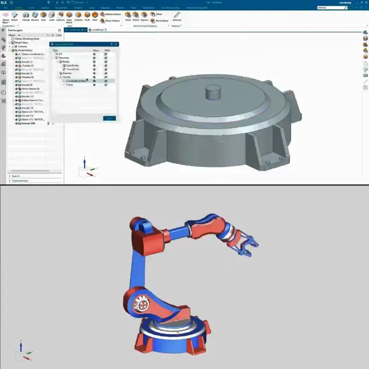
Base plate — part modeling in Siemens NX, with the assembled arm alongside
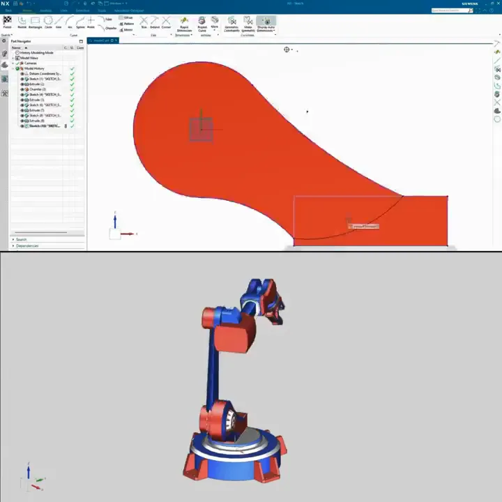
Arm link — sketch profile before extrusion
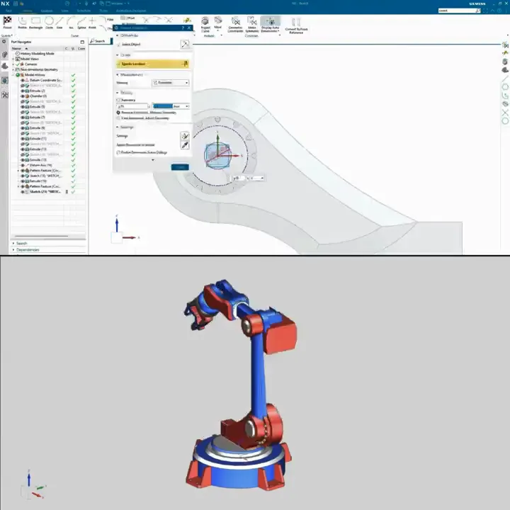
Wrist joint housing — feature detail
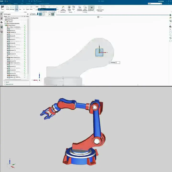
Arm link — dimensioned sketch profile
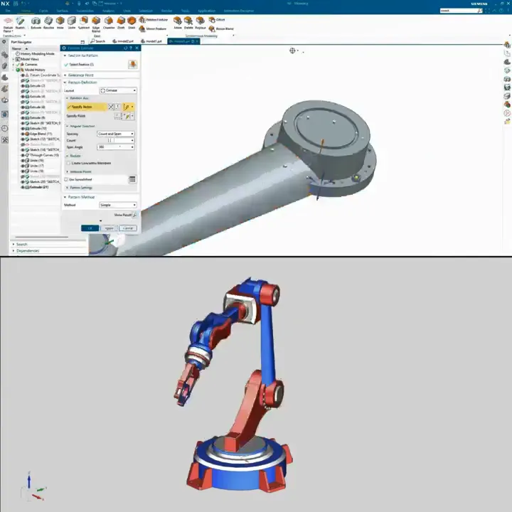
Flange — circular bolt-hole pattern
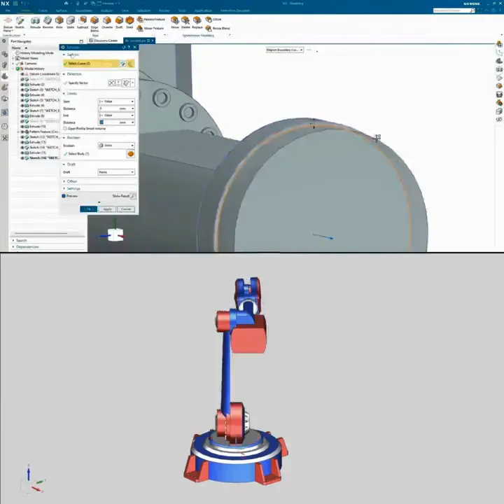
Base housing — extrude feature detail
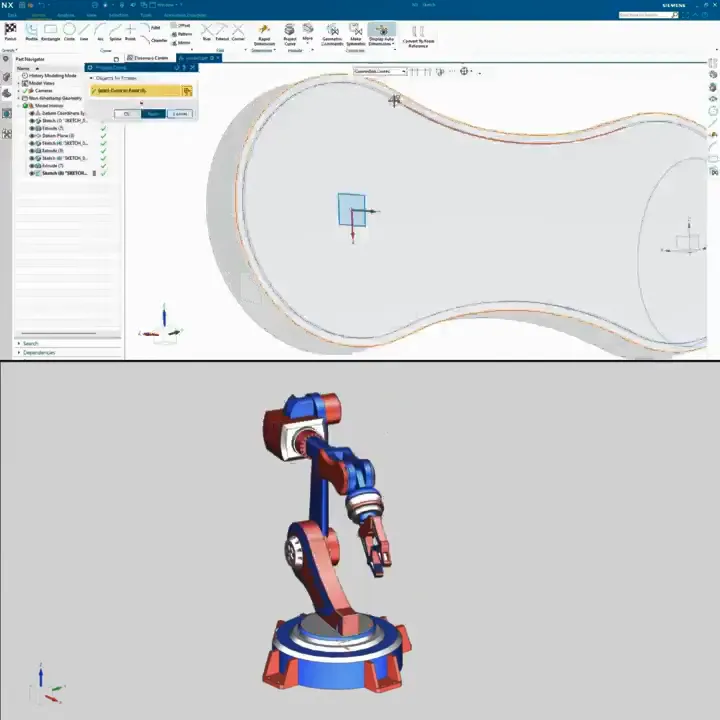
Arm link — construction geometry for a swept profile
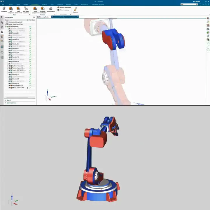
Assembly constraints — positioning a component into the arm
Full assembly and motion simulation walkthrough — Siemens NX