Project
V6 Engine CAD Design — Creo Parametric
Technology
Year
2026
Context
Personal project to design a complete V6 engine CAD model in Creo Parametric, inspired by real-world automotive engine architecture, aimed at understanding how individual mechanical components are designed, positioned, and integrated into a sophisticated powertrain system.
Constraints
The engine's major systems — block, cylinder heads, valve train, crankshaft and piston assemblies, camshaft drive, and intake/exhaust manifolds — had to be modeled to realistic automotive geometry and integrated into one large, correctly assembled powertrain model.
My Role
Sole designer: modeled every major engine component and sub-assembly, integrated them into the complete V6 architecture, and iteratively refined geometry and assembly relationships for design consistency.
Approach
Component modeling. Major engine components — engine block, cylinder heads, pistons and connecting rods, crankshaft, camshafts, valves, rocker arms, and intake/exhaust manifolds — were each modeled individually to realistic automotive geometry using advanced parametric part modeling.
Large assembly design. Components and sub-assemblies (piston sub-assemblies, cylinder head sub-assembly, camshaft housings) were integrated into a single large assembly, with the relationships between major engine systems defined explicitly rather than treated as isolated parts.
Automotive architecture. The layout follows real-world V6 engine architecture: a V-bank cylinder head arrangement over a common crankcase, with camshaft-driven valve trains and intake/exhaust manifolds routed around the block.
Engineering visualization and refinement. Section views and cutaways were used throughout to inspect internal geometry — valve train timing, piston-to-crankshaft relationships, manifold routing — driving iterative refinement of both geometry and assembly relationships.
Results
Complete, correctly assembled V6 engine CAD model in Creo Parametric, integrating the block, cylinder heads, valve train, crankshaft and piston assemblies, and intake/exhaust manifolds into one coherent automotive powertrain architecture.
Limitations
No combustion, thermal, or structural simulation was performed — the focus was CAD architecture, large-assembly methodology, and automotive mechanical layout, not performance or durability validation.
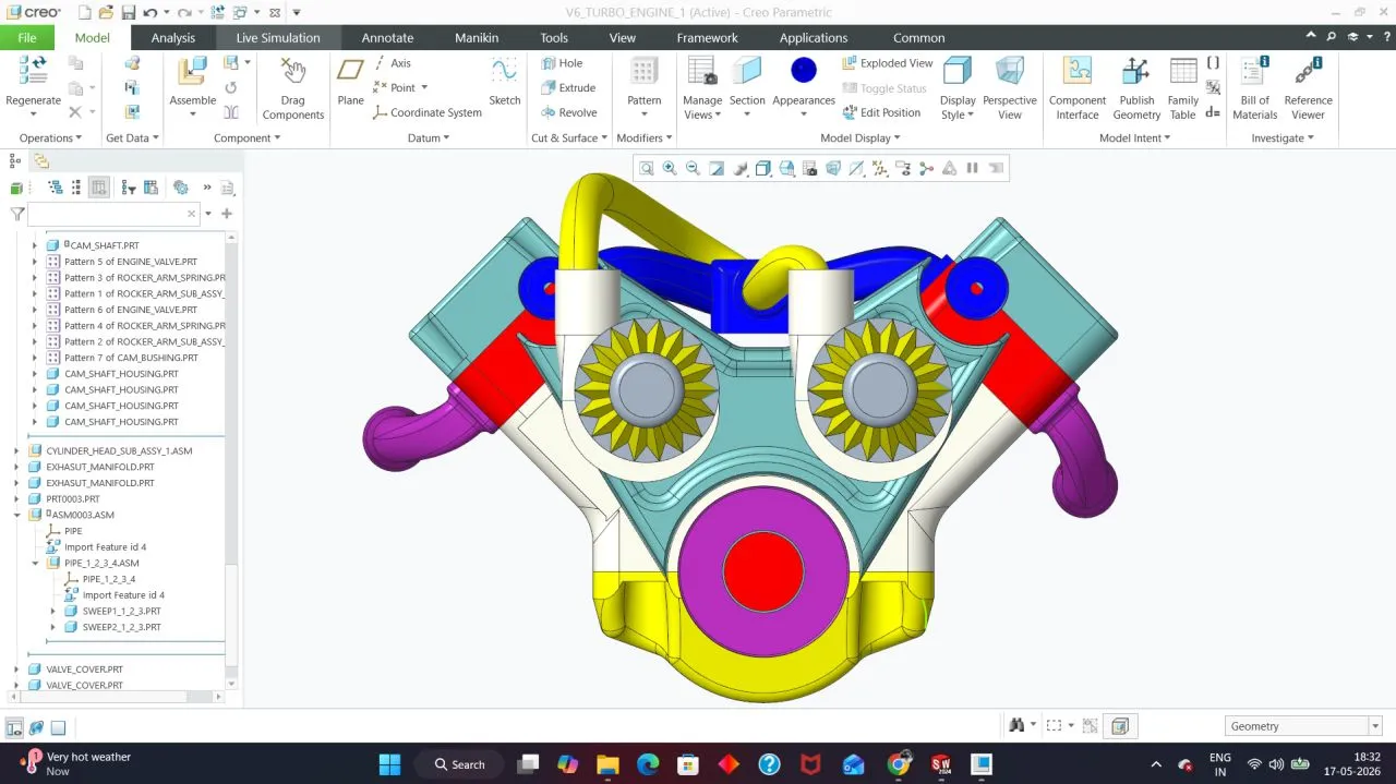
Assembled V6 engine — block, cylinder heads, and intake/exhaust manifolds
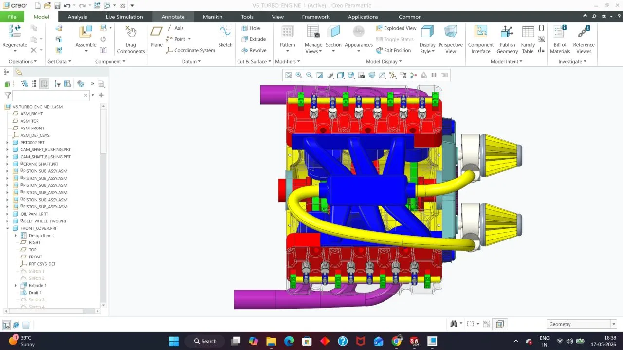
Front cutaway — full engine assembly, camshafts to crankshaft
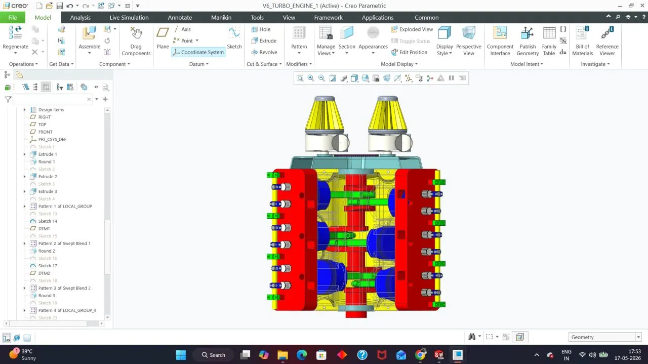
Cylinder head cutaway — valve train and camshaft detail
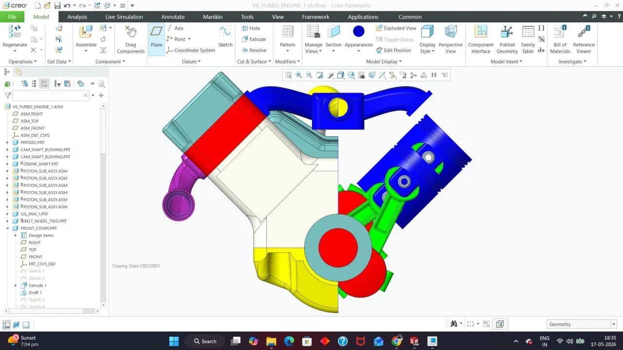
Piston, connecting rod, and crankshaft assembly
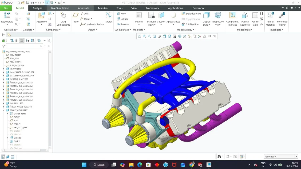
Cutaway view — timing chain and valve train architecture
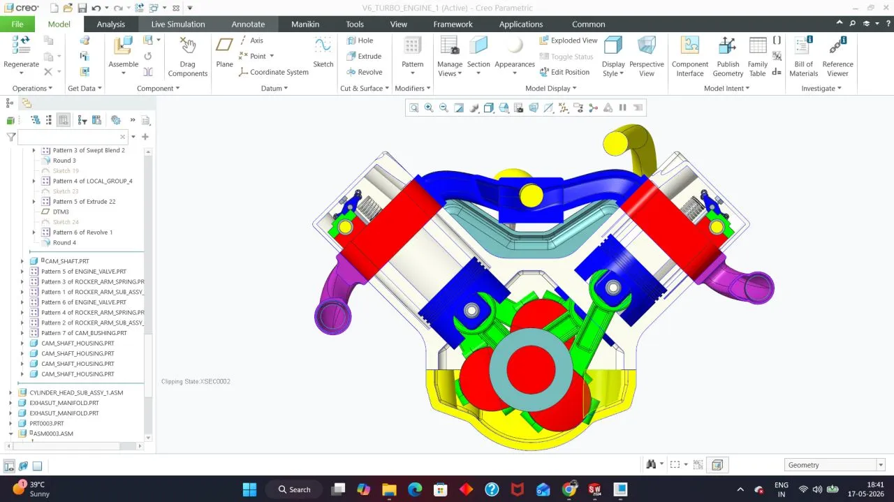
Valve train — rocker arms and camshaft, front cutaway
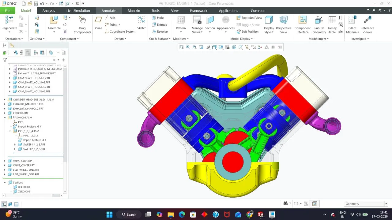
Camshaft drive sprockets — timing detail
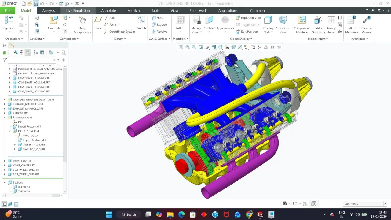
Valve train close-up — rocker arms, springs, and camshaft