Design for Manufacturing: Lessons From the Shop Floor
A part can be structurally perfect and still be a nightmare to produce. Design for Manufacturing (DFM) is less about following a checklist and more about developing the habit of asking "how does this actually get made?" before the design is frozen.
Tolerances stack up faster than you think
Tight tolerances feel safe on a drawing, but every added tolerance increases cost and rejection rate down the line. On an assembly with several mating parts, a tolerance stack-up analysis usually reveals that only one or two dimensions actually need to be tight — the rest can be relaxed without affecting fit or function.
The two standard ways to combine tolerances give very different answers. Worst-case stacking assumes every dimension lands at its limit simultaneously; the statistical (root-sum-square) method assumes independent, normally distributed variation:
For a stack of five ±0.1 mm dimensions, that's the difference between a worst-case budget of ±0.5 mm and an RSS budget of about ±0.22 mm — which is exactly why an assembly toleranced by simple addition is so often needlessly expensive. Once you know the total budget the assembly can tolerate, allocating it back to individual dimensions is a short loop:
function ALLOCATE_TOLERANCE(dimensions, T_target):
    T_rss ← sqrt(sum(T_i^2 for T_i in dimensions))
    if T_rss <= T_target:
        return dimensions            # already within budget, relax if desired
    scale ← T_target / T_rss
    return [T_i * scale for T_i in dimensions]
Internal corners need a reason to be sharp
A sharp internal corner is trivial in CAD and expensive (or impossible) in machining, since it requires a tool with zero radius. Adding a fillet that matches a standard tool radius early in the design avoids a redesign cycle after the first quote comes back.
Prototyping method should match the failure mode you're testing
3D printing is fast and cheap, but it doesn't tell you anything about a part's behavior under real material properties, injection-molding shrinkage, or machining-induced residual stress. Matching the prototyping method to what you're actually trying to validate — fit, function, or structural performance — saves a lot of wasted iterations.
Case study — mounting plate, first article rejection
A batch of ten aluminum mounting plates came back from the machine shop with six parts rejected on a single ±0.02 mm flatness callout that had been copy-pasted from an older drawing and never actually needed for the assembly to function. Reworking the drawing to ±0.1 mm on that feature — and confirming the real constraint was a ±0.05 mm hole position instead — took the rejection rate on the next batch to zero, at a lower unit cost.
Nothing about the part's function changed. Only the drawing did.
The real lesson
Most DFM mistakes aren't technical, they're a communication gap between design and the people running the machines. A five-minute conversation with a machinist before finalizing a design catches more issues than another CAD review ever will.
Related Project
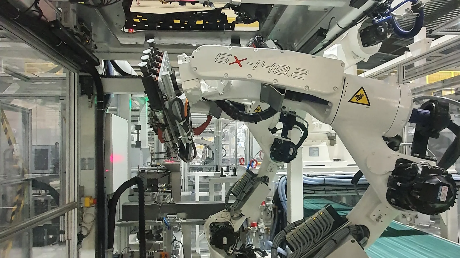
Robotic Fastener Quality System — AUTOCLIP Line
More